 Back to docs
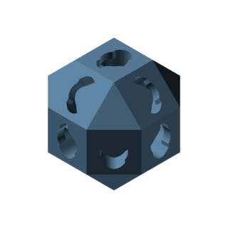 hub
hub
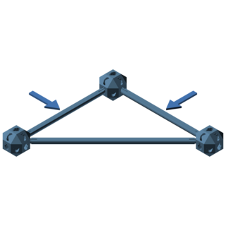 leg_strut
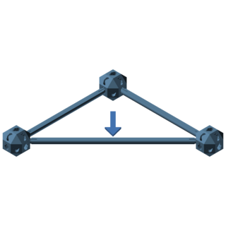 hyp_strut
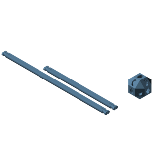 truss_set
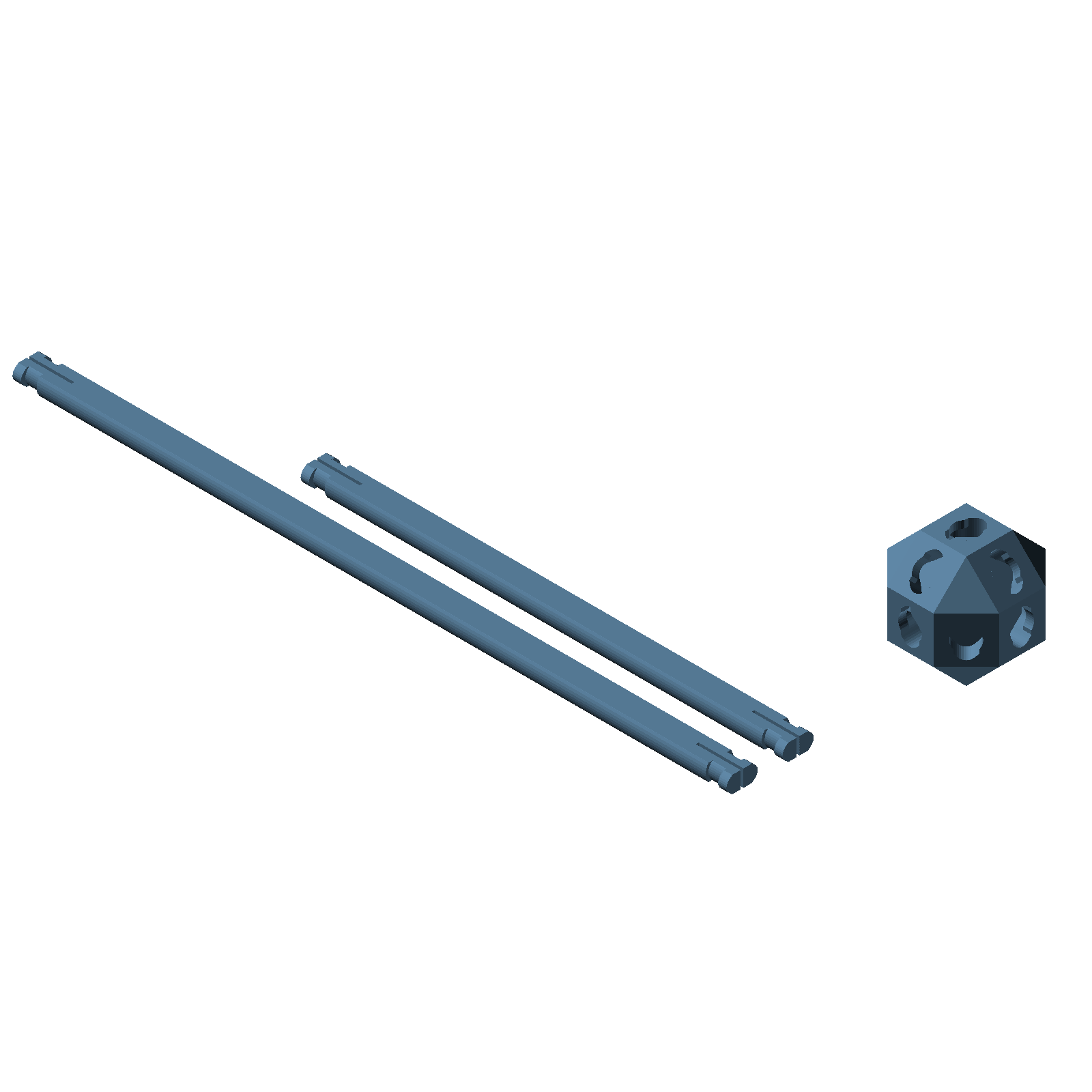
truss_set() generates a hub, a leg strut, and a hyp strut.
Customizing truss parts with OpenSCAD parameters
The truss group has four modules: hub, leg_strut, hyp_strut, and truss_set. hub connects struts together, leg_strut is the straight strut, hyp_strut is the longer diagonal strut, and truss_set generates all three parts at once in a print-ready configuration.
The truss system uses canonical dimensions, so the struts take no dimensional parameters at all. hub and truss_set share the same set of parameters. Here is a hub called with every parameter spelled out:
| do_nut_pockets | hub only: when true (default), the hub gets pockets sized for captive m3 nuts and through-shafts for m3 machine screws. Set to false to leave them out. |
| nut_thickness | hub and truss_set: nut thickness in mm (default global_default_nut_thickness, which is 2.6 mm for standard m3 nuts). |
| nut_width | hub and truss_set: nut width across flats in mm (default global_default_nut_width, which is 5.5 mm for standard m3 nuts). |
| nut_clearance | hub and truss_set: added to the nut width where each nut pocket is cut (default global_default_nut_clearance, which is 0.2 mm). |
| echo_parameters | when true (default), the OpenSCAD console echoes the full parameter list when you preview or render the module. |
If you leave a parameter out of the module call, that parameter will just have the default value. For example, these are all valid module calls:
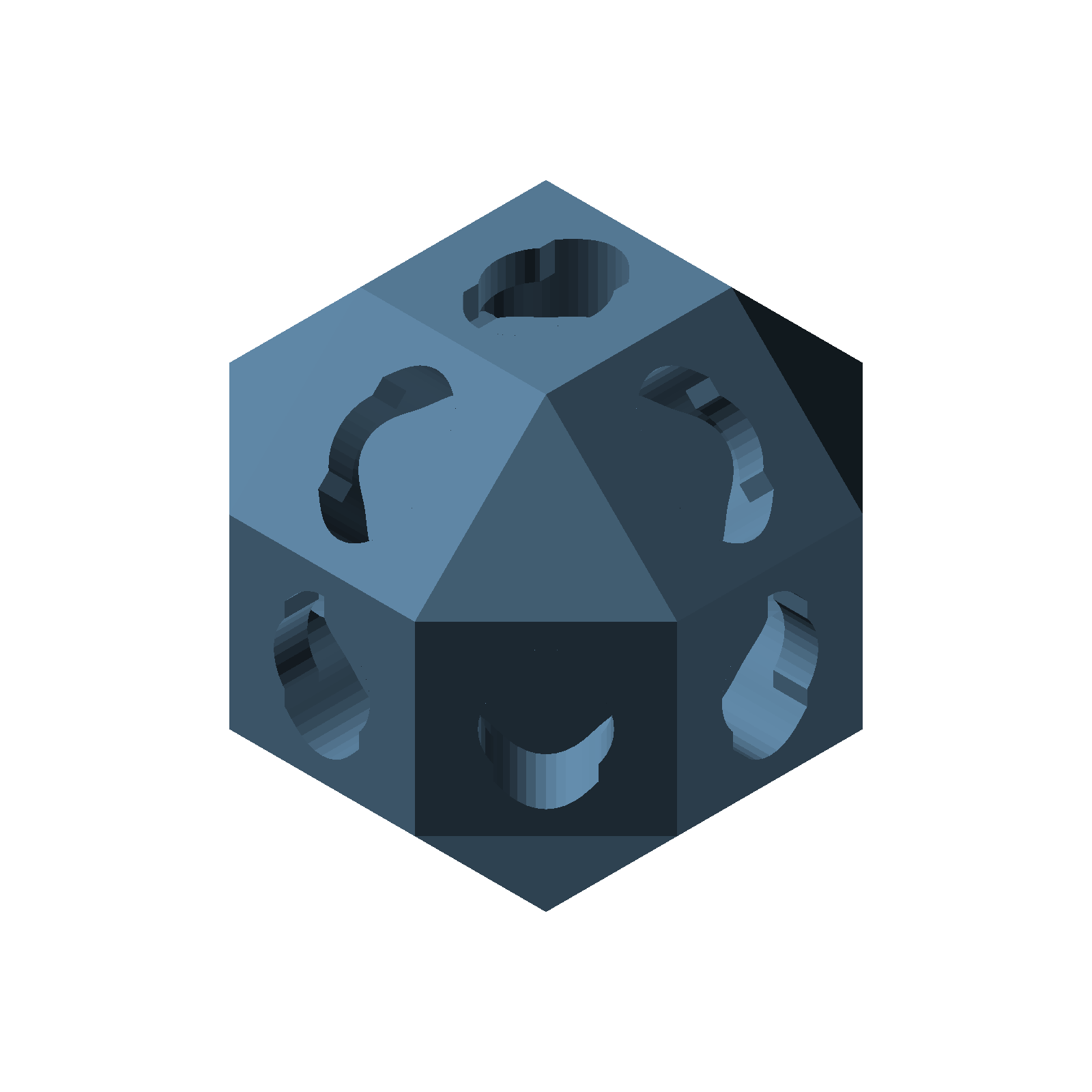
Hubs have limited rotational symmetry; be sure they are all oriented the same way when assembling a truss structure.
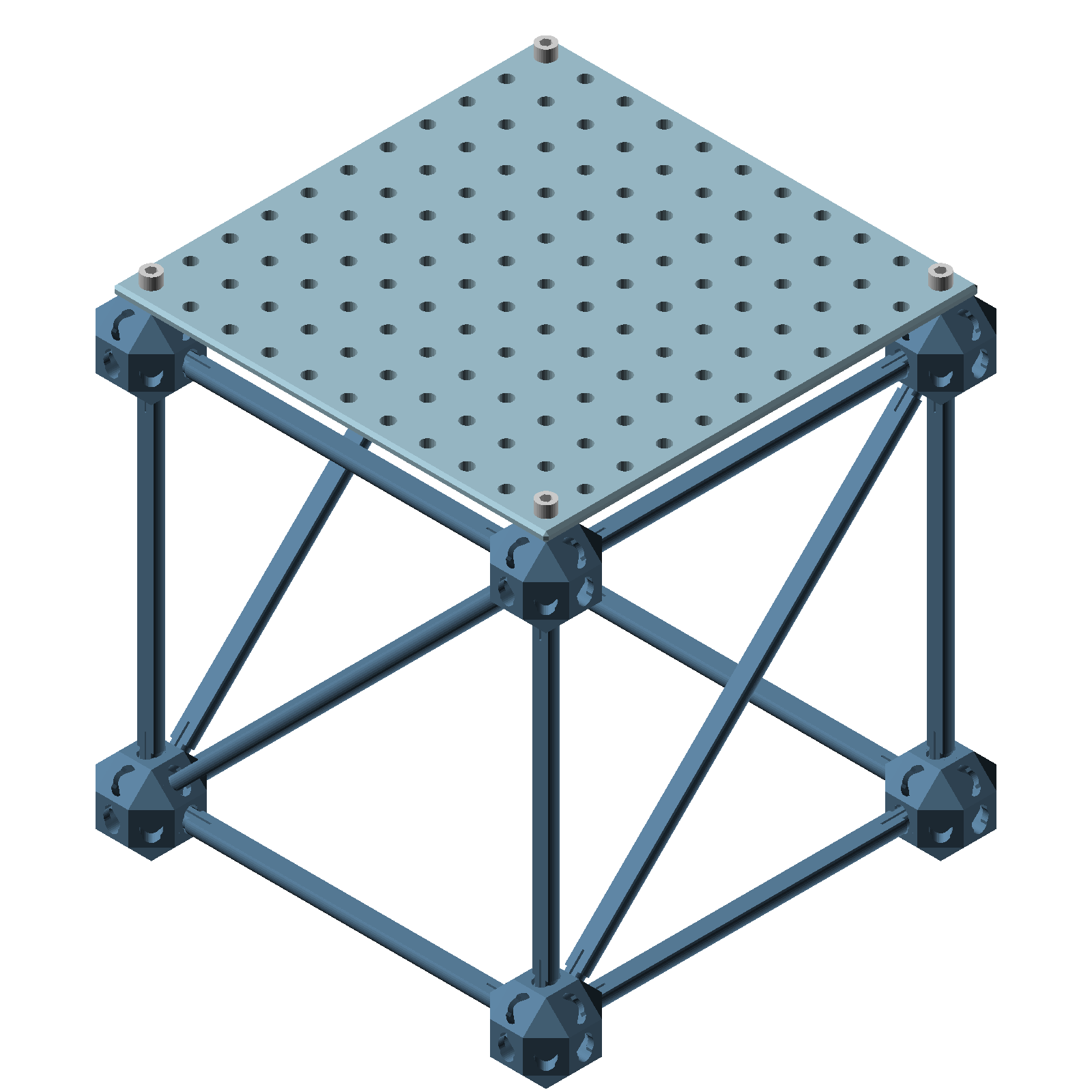
An 11×11 plate covers a truss unit, its corner holes landing on the four hub mount holes.
Using truss parts
Start assembly with just hubs and leg struts. A structure made from only these two parts is easy to change, so keep adding leg struts and moving pieces around until the final size and shape of the truss structure is known.
It's normal for individual connections and the structure as a whole to be wobbly at this stage.
Once the structure is settled, add hyp struts along the diagonals to make it completely rigid.
Make sure all the hubs are oriented the same way. The hub has limited rotational symmetry, so a hub that is twisted relative to its neighbors will not line up with the struts coming in from the rest of the structure.
An 11×11 plate fits neatly onto the side of a truss unit, its corner holes corresponding to the mount holes of adjacent hubs. A part that is 11 standard prpol units long is 10 cm between the holes on the ends, matching the 10 cm spacing between hubs.
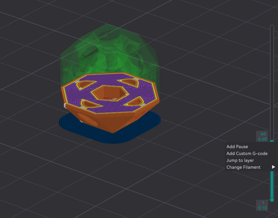
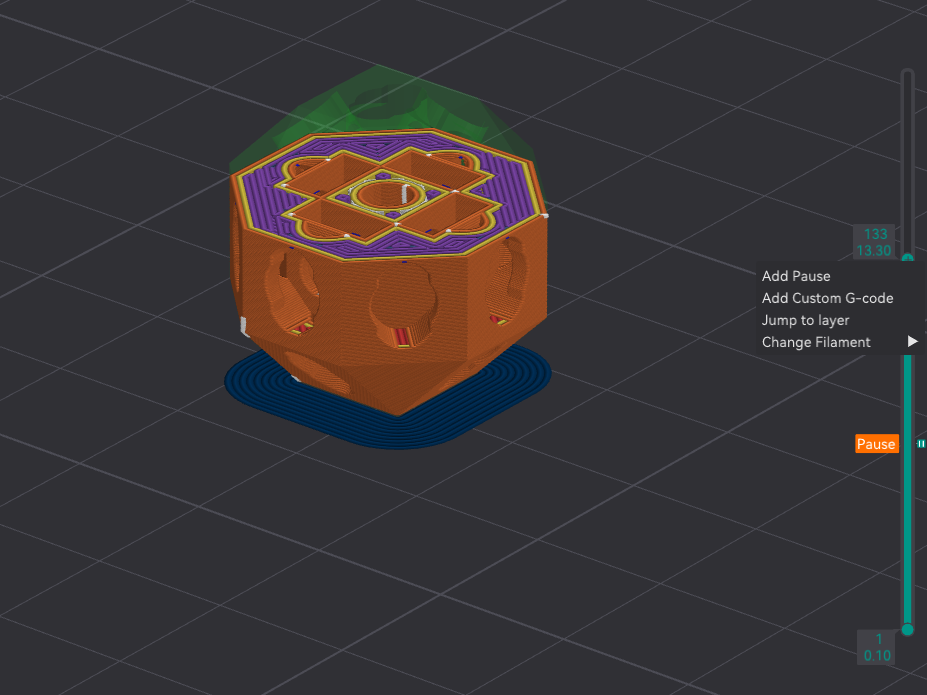
The first g-code pause layer when printing a hub with captive nuts. This is where you will insert the first of six nuts.
The second g-code pause layer. This is where you will insert four nuts.
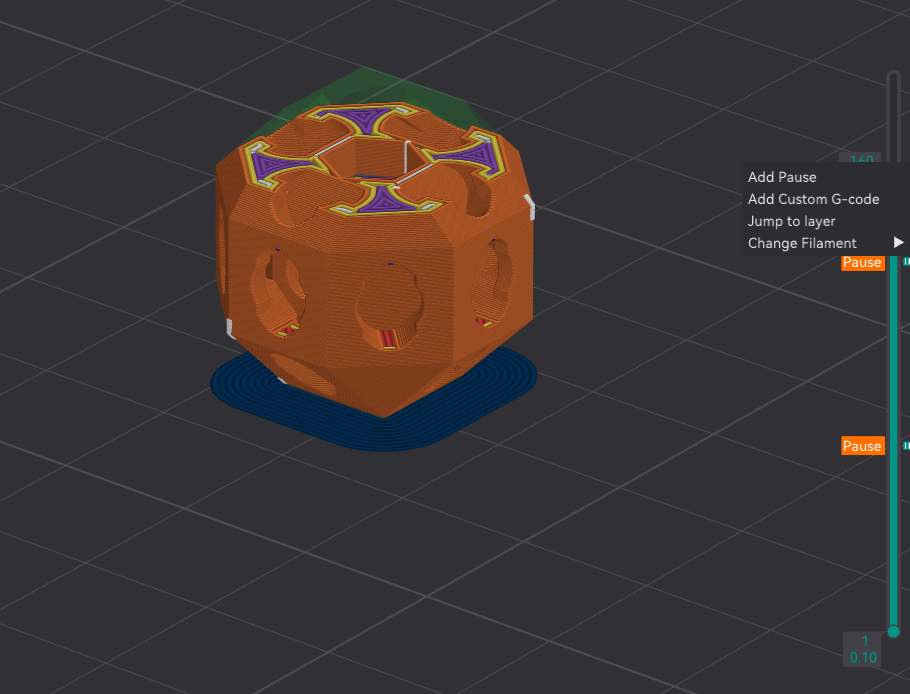
The third and final pause layer. This is where you will insert the last nut.
Printing truss parts
General tips for printing hubs and struts:
- Do not use supports when printing hubs. Hubs are designed to be printed without support material.
- Add a brim to hubs when printing to help prevent them from coming unstuck from the print bed.
- Use a layer height of 0.1mm when printing hubs. This will help ensure dimensional accuracy.
- Print leg struts in a different color from hyp struts. This will help make organizing them into separate containers or trays easier.
- You don't have to print all hubs with captive nuts, even if you plan on using this feature. It's a good idea to print hubs with nuts in a different color from hubs without nuts to make organizing them easier.
Printing hubs with captive nuts:
In order to print hubs with captive nuts, you have to use g-code-initiated pauses. When you set up the print job with these pauses, your printer will pause at the layers you specify so you can insert m3 nuts into the internal nut pockets of hubs. Here's how to to do this in OrcaSlicer:
- First, slice your model. Then in the print preview tab, use the slider on the right of the viewport to see individual layers.
- Find the layer that corresponds to the first layer where material is being placed over the top of the lowest nut pocket. This lowest nut pocket is hexagonal in shape. The layer just before that layer is the one where you will have the first pause. The accompanying figures show what this and the other target layers look like.
- To mark a layer to have a pause, right click on the layer selection slider button, then choose Add Pause.
- Next find and mark the layer that corresponds to the last layer before material is added over the top of the four "equatorial" or middle nut pockets. These nut pockets are rectangular in shape.
- Mark the layer that corresponds to the last layer before material is added over the final hexagonal nut pocket at the top.
- Slice your model again to have OrcaSlicer include the pauses in the output g-code.